3-DREAMERS
Countdown Till Presentation


28 April, 2014
Time is up!
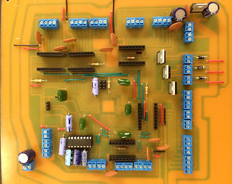
On Friday, April 25, the team presented their project to a panel of professors and people from industry. Over 20 people came out to support the team. Unfortunately, the RAPTER was not working perfectly yet. The team is still calibrating the motors and the extruder to create more accurate parts. However the team did print key chains for the panelists and for themselves to show their progress. The picture on the left is RAPTER. It is missing some of the acrylic glass covering but those peices have been removed to allow people to more easily look in and see all the components. The picture on the right is our team just after giving our final presentation.
Thank you to all of our professors, mentors, family, and supporters for taking this journey with us. Kepp on dreaming!
20 April, 2014
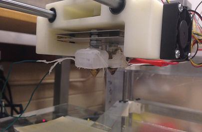
THE RAPTER IS PRINTING!! This is the first week the 3-Dreamers have been able to put all of the sub systems together and print something! The goal was to print a cube however with some issues within the program of the RAPTER, a rectangle was printed. The progression of this is shown in the figure below.
As one can see, the first print was extruding not much of any shape. The second print was a uncontrolled diagonal whereas the third was more controlled. The fourth print gave us the best print so far, a rectangle. With more debugging, the RAPTER will be printing what is expected!
An additional motherboard was created with a temperature control for the extruder. This element was left out in the early attempts; however the temperature control of each heating element in the extruder is an important addition and will improve the RAPTER!

13 April, 2014 Weekly Update
EXTRUDER- The new extruder shown below has been implemented onto the printer and was tested with the x-y motion of the printer active. While the extruder does seem like it will keep up with the speed of the x-y motion just fine but the ABS did not seem to want to stick to our printing surface. To fix this problem tests will be run to see if the ABS will stick to a platic tray better allowing the ABS to stay in place long enough to harden. The new design is shown below. This new design uses two motors to feed the two types of filiment through the nozzles instead of the earlier switching mechanism first looked into.
HEATED PLATE- The heated plate has been finished and is still awaiting testing with the mother board.
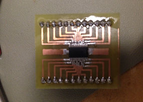
CIRCUIT DESIGN- The circuit board was completed and all parts have been solded to the board. The images below are of the motherboard. The board was designed in Express PCB then etched using a solvent in order to get the design onto the copper board. This board takes an input voltage of up to 14 volts then is put through a voltage regulator that reduces the voltage to 3.3 volts. This voltage is then used to run all logic on the board. The board is capable of running 9 motors, 3 fans, 3 heaters and 8 limit switches allowing us to controll the entire printer while still being able to replace motor controllers fairly easy if burnt out.
MICROCONTROLLER- The X-Mega currently has the code sucessfully programmed on it and is is currently able to run all three axes simultaneously. Here shortley the xmega will be able to control the three heaters as well as the fans and limit switches.
SOFTWARE- Code was implemented to x-y and z axis in order to try and simulate printing of a small block. However as of right now the code is not running consitenly. This is being looked into and hopefully will be fixed within the next couple days. After the bug is found testing will continue in order to make any final adjustments needed.

6 April, 2014 Weekly Update
EXTRUDER-Two more heating blocks were machined after more refinement. Proper cleaning and maintenance methods have been researched for the hot block and the nozzles. Cold end and Hot end on Friday extruded consistently with no errors as optimal temperatures were tested. Operating temperature refinement continues.
HEATED PLATE- From sample data taken of the table at different operating temperatures, a best fit trend line has been created linerizing the temperature region the table should be operating at for more accurate temperature settings. Refinement of the temperature control algorithm continues.
CIRCUIT DESIGN - The motherboad has been printed and eched. Holes still need to drilled.
MICROCONTROLLER- The x mega has had code sucessfully ported and issues surrounding the x mega fuctioning have been resolved.
SOFTWARE- Code operating the gantry has been sucessfully sent to the individual motors, however only one axis works as expected at the moment. The PC and Controller are communicating correctly and operating inside the structure.

30 March, 2014 Weekly Update
EXTRUDER – The design of the extruder has moved away from the switching mechanism to a single mechanism consisting of a pulley and bearing. It has been tested and is working properly. However, two stepper motors will be required in order to feed both plastics now.

HEATED PLATE – The heated plate has been built. The code to maintain a constant temperature is being refined currently.
CURCUIT DESIGN – The final circuit design for the AtxMega128 is almost complete

MICROCONTROLLER – Communication has been enabled on the AtxMega128. The code made previously on the Atmega128 has been ported over but has yet to be tested.
SOFTWARE – Large progress was made this past week for software. The flow control errors have been resolved over a new RS232 cable. The embedded software is now able to interpret step values for X and Y greater than 256. Tests performed demonstrated that the gantry is now moving in the proper directions. The next step is to include the Z values in order to test the printer in a dry run. Additionally, an error of a significantly large value sent occasionally for both X and Y needs to be resolved prior to the dry run in order to not allow the motors to exceed their max range.
23 March, 2014 Weekly Update
STRUCTURE - The structure and gantry are awaiting the completion of the other subassemblies for final assembly.
EXTRUDER - The hot end is now reliably melting and extruding ABS filament. Further testing will be done this week for PVA extrusion.
HEATED PLATE - is undergoing assembly and testing.
SOFTWARE - Some flow control errors were solved thispast week. There are still some communications bugs to be worked out, but progress is being made. The embedded code is in the process of being ported to the production microcontroller.
CIRCUITS - The new stepper motor drivers have been tested, and are operational. These are now being used for motor control for the remainder of the testing required, and will be integrated into the final design. The system motherboard is being designed, now that the necessary components are known.
16 March 2014 Weekly Update
GANTRY- The final design of the gantry (X,Y, and Z directions) have been made. The use of three threaded rod steppers was needed for the Z platform. This allows the platform to be adjusted and prevents binding. The original design using one threaded rod stepper had binding issues. All three axes are moving!


STRUCTURE- The hinged door can be seen above. These pictures do not show the acrylic glass that surrounds the enclosure as it was removed to facilitate assembly. Each panel of acrylic glass is secured with four screws.
SOFTWARE/MICROCONTROLLER- Our software is sending lines of G-Code to the microcontroller via RS232. Our embedded software is able to interpert the communications and drive the appropriate steppers.
CIRCUITS- A4988 driver boards have been purchased to allow easy replacement during testing in the case of failure. The boards can handle up to 2 amps of current when properly cooled allowing for more torque and faster print speeds. The driver board can be seen below.

2 March 2014 Weekly Update
STRUCTURE- The structure has now been encased in acrylic glass.
HOT END- There is too much friction in the system to allow for proper extrusion. We are in search of a sample of PTFE tube. This tube has a low coefficient of friction so the filament will more easily be extruded.
COLD END- We are currently designing a tensioner to allow for more than one filament size to be used with this product.
CIRCUITS- Design of the final board is being designed.
23 February 2014 Weekly Update
STRUCTURE- The x,y and z axes bearing have been printed and implemented within the structure! This means that the basic structure is complete and it is waiting for the print head and heated plate to be added on within the next couple of weeks. Testing on the movement of the axes was done. Further improvement is necessary.
MICROCONTROLLER- Coding was implemented within the testing of the structure. The x,y and z axes can be driven simultaneously!
HOT END – Various insulation methods such as ceramic tile, Aerogel, Kevlar and an air gap have been tested to ensure the filament will reach melting temperature gradually. Filament was able to be extruded using the Aerogel and Kevlar methods.
COLD END- The smaller prototype was tested and improved upon. A spring was added to the switching mechanism to help the system return to a neutral position. New gears with more teeth were also printed in hopes minimizing the gears slipping when pulling filament through.
SOFTWARE- MATLAB functions were used interpret G-Code. MATLAB was able simulate how the printer will print a cube. The next step is to have Python interrupt G-Code.
16 February 2014 Weekly Update
STRUCTURE - The parts for the gantry have been cut and drilled and have been prepared for assembly in hopes of having a testable gantry next week. A change in the z - axis has also been made in CAD in order to attempt to prevent any binding in the bearings during operation. New gears for feed device have been printed to allow for proper set screw configuration.
HOT END - Thermocouple testing was conducted to see if the hot end of the printer would be able to maintain certain temperature given to the system.
MICROCONTROLER - The new DRV8834 motor controller was integrated into the circuit and was used to test the x-axis movement with two motors. More testing of the small prototype was completed as well as testing the error checking through the microcontroller.
Circuits - Two styles of the DRV8834 were designed and printed. 2 of each of the boards shown below were completed this week and have been implemented and testing has begun. These boards will only be used for the prototype and testing while the final board won't be plug and play.


2 Feb 2014 Weekly Update
9 Feb 2014 Weekly Update
STRUCTURE – The CAD work for the structure has been completed. The Gantry parts that were to be printed out of ABS plastic have finished and been collected. Bearings have been inserted into the appropriate printed blocks. To protect the printed parts from the heater blocks, different types of insulation material and combinations of materials are currently being tested.
CAM SOFTWARE – After abandoning the idea of using serial protocol software, Matlab functions were written to interpret and decode several different versions of G-Code.
MICROCONTROLLER - The coding for the microcontroller is currently being updated to reflect the shift to writing G-Code interpretation functions, instead of using serial protocol software. More PCB's are also currently being printed.
HOT END – The modified heater blocks have been machined and obtained, along with nozzles that were purchased. Matlab code has been written and paired with a Thermocouple circuit to monitor and maintain the temperature of the heater block being tested. One of the heater cartridges blew out, so further inquiry into the maximum power and current ratings is being conducted. The following picture is the new heater blocks and the new nozzles.
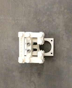
COLD END – The final design for the cold end, including the swinging mechanism and gears notched to pull the filament through, has been printed and assembled. The following picture is the printed cold end.
SUPPORT MATERIAL – Further testing into the material properties of PVA is being conducted to obtain a more definitive melting temperature.

PARTS HAVE BEEN RECEIVED - The parts ordered from RobotDigg were brought in early this week. With the majority of parts in hand the prototypes were refined to include them.
STRUCTURE - Manufacturing has continued on CAD. Certain parts will no longer need to be machined. These parts added onto the design will be made of plastic. They will be printed once their design has been finalized.
ENCLOSURE - The L-angle aluminum for the enclosure was purchased at Prescott Steel. The aluminum was cut and drilled. The picture below shows the enclosure assembled.

SUPPORT MATERIAL - PVA dissolve testing has been extended to include weak acids as well as temperature variations of water.
HOT END PROTOTYPE - With the new parts came the resistors intended to be used on the heater blocks. A new heater block was made to be able to attach the resistors in place and continue testing. Below is a picture of the newly designed heater block.

26 Jan 2014 Weekly Update
STRUCTURE - Manufacturing continued on the system supports and enclosure. The design of the internal mechanisms is progressing, and most of these have been designed in CAD in preparation for further testing and manufacturing.
MICROCONTROLLER - RS-232 communications have been implemented between the ATMega microcontroller and a host PC. The PC is running a Python script and can be used to control the stepper motors via the serial link. Although a microcontroller evaluation board is being used at present for development, a controller surface mounted to a PCB was finished this week and will be tested in the near future.
CAM SOFTWARE INTERFACE - Because the host software selected has little solid documentation, research into the serial protocol between the host software and the printer is continuing.
COLD END PROTOTYPE - The steppers were used this week for testing the cold end filament feed system and switching mechanism.
HOT END PROTOTYPE - This week saw more testing in regards to filament melting and extrusion. The team is determining ideal operating temperatures, time required to raise the hot end to sufficient temperatures to begin extrusion, and overall power required for the hot end.
SUPPORT MATERIAL -PVA samples were received, and the team is experimenting with various methods to reduce the time required to dissolve this material once a printed part has been completed.
19 Jan 2014 Weekly Update
PARTS HAVE BEEN ORDERED- The majority of the parts to construct the prototype have been ordered from RobotDigg. Using this company we have been able to keep well within our budget of $1000.
MICROCONTROLLER AND SPEPPER DRIVER- The ATmega microntroller has been programed to control steppers through a stepper driver. This allows easier control of the steppers. Prior to this point the steppers have been condrolled directly by the microcontroller through MOSFETs.
ENCLOSURE- Manufacturing has begun on the enclosure made of L-angle aluminum.
COLD END PROTOTYPE - Special gears have been designed and printed to allow the plastic filament to pass through the gears to the hot end. As of now it has not been tested with the hot end. SEE VIDEO BELOW